


FECORE - Long Distance Microwave Second Attempt, experiment FAIL
Dear Readers,
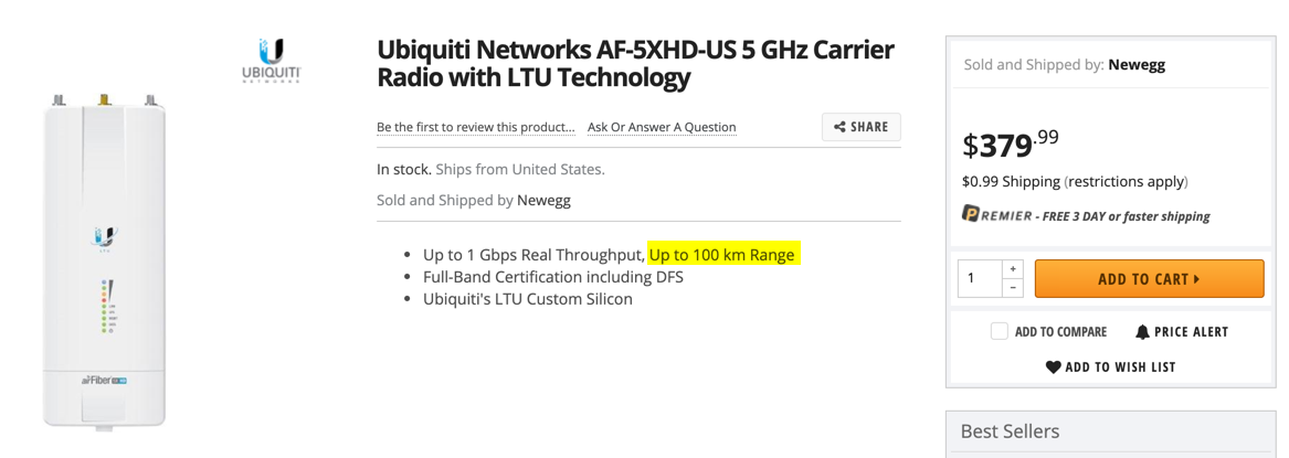
FECORE is using a Ubiquiti AF5XHD Carrier which ONLY HAS A POWER RANGE OF - 100 kilometers.
How on Earth (flat or globe) do they claim to be attempting a new 307 km world record distance microwave link?
Folks, they have no clue what they are doing!
-
The FECORE report is listed here for your review
https://fecore.org/long-distance-microwave-second-attempt-report/
Below is a transcript of the report (less pictures). Our comments on the test will be forthcoming...
Long Distance Microwave Second Attempt Report
by Sandor Szekely | Sep 28, 2019 | Long Distance Microwave Transmission, News & Updates, Projects
Our second attempt for setting the new microwave transmission world record distance was unsuccessful. We did not reach our goal to connect the antennas over the world record distance, but we gained a lot of experience and valuable information from the data we gathered.
It is not easy to set a world record – indeed.
FECORE made a 2nd attempt to set a new 5GHz microwave transmission world record in Hungary, on the 20th – 21st of September 2019.
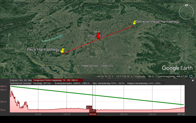
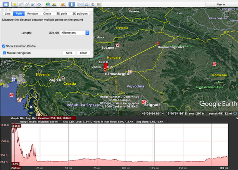
The two positions were the same as last time, giving a 307 km distance between the two towers:
3 people were on the Pecs side, Stefan P, Gabor and Attila a Hungarian microwave professional, 2 people were on the Debrecen side, Sandor Szekely with Viktor a Hungarian microwave professional.
On Friday 20th September we installed the new AF5XHD radios with the larger antennas on the towers by 11 AM and set the vertical alignment to 0°. We aligned the antennas to our reference line, heading 241° on the Debrecen side and 58° on the Pecs side according to google data. The heading was confirmed by using landmarks from Google Earth and with a compass on the ground.
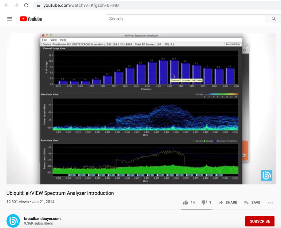
We used the Ubiquiti spectrum analyzer software to monitor the frequencies and the Ubiquiti alignment tool.
We started with the Pecs antenna as the slave monitoring the spectrum analyzer and the Debrecen antenna as the master broadcasting the beacon signal. Below is a picture of Stefan at the Pecs location.
By turning one antenna at a time, we first swept the antenna at Debrecen in small increments of about 1 degree from our established reference line. The antenna at the Debrecen side was then swept a total of 20° from the far left (at 231° SW) to the far right (at 251° SW) whilst transmitting the beacon signal and the Pecs side scanning with the spectrum analyzer. The Pecs side then rotated the antenna to a new heading by turning approximately one degree, and the Debrecen side started to sweep the antenna in small increments backwards from the far right to the far left position.
After testing several headings we switched the master to the Pecs side transmitting the beacon signal and Debrecen became the slave. Again we used the spectrum analyzer software and the built-in alignment tool.
None of the configurations resulted in a connection. We tried several different frequencies, bandwidths, and RX transmission rate settings without a successful connection1. At 3:30PM we came down from the towers as the wind was increasing and the temperature was cold.
We set up an FECORE meeting to brainstorm on the experiences of the day and to look for new ideas to develop for the next day.
Our focus was on the horizontal heading precision. The question arose, “Can we trust the google maps data?”
It showed a heading of 241° SW from Debrecen and 58° NE from the Pecs side.
Modelling the heading on the Azimuthal Equidistant (AE) map showed a few degrees difference to the google data, equaling 244° SW on the Debrecen side, and 61° NE on the Pecs side.
On Saturday we rotated the antennas with an electrical turntable pole controlled from ground level on both towers. The antennas were moved horizontally at approximately 2.5° increments and the relative heading was shown on the display of the turntable equipment.
We swept across the +-15° range from the new reference line using AE headings in small increments one antenna at a time just as we had done on the previous day.
We worked from 9 AM until 5 PM without being able to establish a link between the two locations.
After evaluating the test, we found the following possible reasons and discussed some potential solutions:
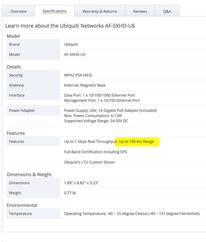
Is the AF5XHD unit with this antenna powerful enough for the 307km distance?
According to the manufacturer’s specifications, it is designed for such long distances.
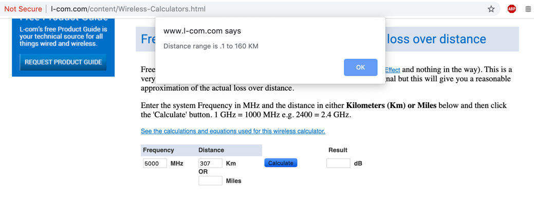
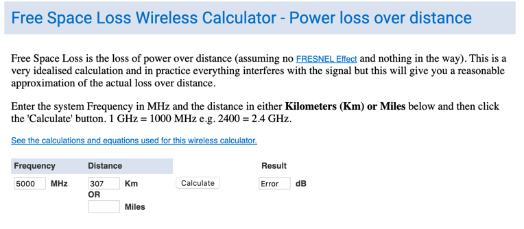
We are going to test the unit on shorter distances of 10-20km, 50-60km and 100+km to measure power loss over distance. We can measure transmitting power and path loss over these distances to calculate dBm level for new the world record distance1.
Was the horizontal aiming precise enough?
To establish the connection between the antennas, we need to be within about 3° LOS (Line of Sight) with a calculated signal loss of 3dB. We swept an area of 30 degrees from both locations several times within the 3° range. So we may conclude that the alignment was precise enough to establish the connection.
We found out from forum discussions on the topic that the Ubiquiti spectrum analyzer software may not be showing real time data and thus may not be quick enough to register alignment within the 2 minutes we paused at each heading position. It appears that it may be required to wait 6 minutes for Ubiquiti spectrum analyzer software display updated data.
We will test the Ubiquiti spectrum analyzer software for delays and check availability of analog scanning devices and a 5GHz signal generator to use for our next alignment attempts.
The electrical turntable was a great tool to set azimuth angles and made sweeping the area very easy. We are planning to design a new instrument we will call SAMAD for Super Accurate Microwave Aiming Device to automatically sweep a specified area defined from the reference line both in horizontal and vertical mode. SALAD was vital to establish extremely long distance laser observations. Perhaps a world record microwave connections will require the SAMAD.
Was the vertical aiming precise enough?
To establish the connection between the antennas we need to be within about 3 degrees of LOS (Line of Sight), both vertically and horizontally, with a calculated signal loss of 3dB. The Ubiquiti software has a 0.1° precision vertical alignment tool, that was confirmed by our microwave expert’s own measuring device. We set the vertical to near 0° both at the Debrecen and Pecs side.
The difference between the AE map headings and the Google Earth headings is 1.5°. That is within the 3° required precision range of the antenna.
The LOS propagation of microwaves is not necessarily a straight line, it may be deflected by atmospheric conditions, especially in the lower atmosphere near the ground.
The Pecs side is at an altitude of 626 meters MSL, and Debrecen is at 169 meters MSL. The beam on the Debrecen side is only 30 meters from ground level with forests along its path. 25km away from the Debrecen tower the ground level drops 30 meters to 100 meters MSL giving the microwave beam extra clearance from the ground2.
The beam at Debrecen side was near the surface where optical density gradients increase with elevation. Leveling refraction may have caused the microwave beam to bend upward above our antenna. We observed the upwards refraction phenomenon on several occasions during the 2016 Balaton laser experiment. The picture below is from the 2016 Balaton observations.
As seen on the pictures of the Chicago skyline from the other side of Lake Michigan the bottom part of the buildings are hidden. We theorize that it is caused by the light bending upwards, due to leveling refraction. This lower elevation optical density profile may be an impenetrable layer for the microwave beam, similar to light. We will do peak to peak mountain tests to avoid lower elevation atmospheric effects in the future.
Did an obstruction in the path of the MW beam cause signal loss?
We checked the whole path of the beam carefully to look for any possible obstructions in the planning phase of the test, and the path of the beam is clear from any high rise buildings, or hills. The beam is crossing a low elevation agricultural area of Hungary, from 70 meter MSL to 115 meter MSL. It starts from Pecs at an altitude of 626 meter MSL and slowly descends with -0.08 degree angle downwards to Debrecen. The critical elevation starts 25km from the Debrecen tower, where the ground level rises to 130 meter MSL. This portion of the beam is passing south of the Debrecen airport with some farmhouses but mostly trees. The beam center clearance reduces to about 20 meter.
In conclusion FECORE will now improve the MWDT (Microwave Distant Targeting) method with the SAMAD and test the antennas over shorter distances to prepare for the next world record attempt.
We try, we fail, we learn, we succeed!
(Written by Sandor Szekely with editorial changes by Robert Scott)
- - - - - - - - - - - - - - - - - - - - - - - - - - - - - - - - - - - - - - - - - - - - - - - - - - - - - - - - - - - - - - - - - - - - - - - - - - - - -
Their equipment:
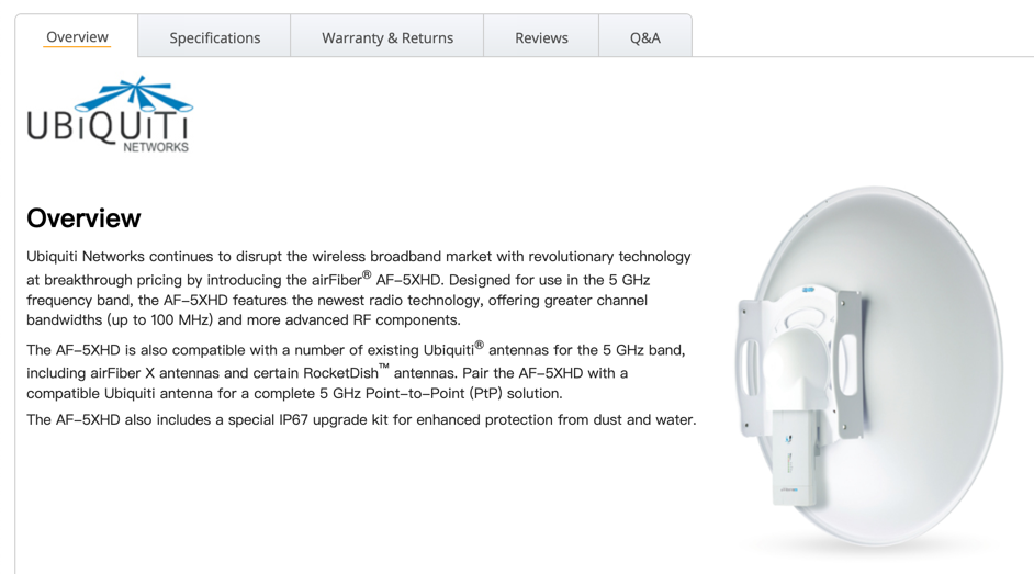
Ubiquiti Networks AF-5XHD-US 5 GHZ Carrier Radio
-
The software they will be using...
- - - - - - - - - - - - - - - - - - - - - - - - - - - - - - - - - - - - - - - - - - - - - - - - - - - - - - - - - - - - - - - - - - - - - - - - - - - - -
Our evaluation of the experiment: STILL IN DEVELOPMENT
Superscript notes:
1. If they understood how microwaves propagate through the atmosphere, they would know that if you can't make a connection at 2.5 Ghz - you will not make it at higher frequencies.
1. They are very much deluded. They will not be setting any world record. No one person at FECORE is a certified/licensed microwave antenna installer.

2. The Google Earth Pro view.
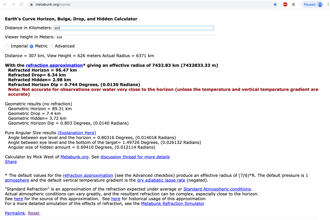
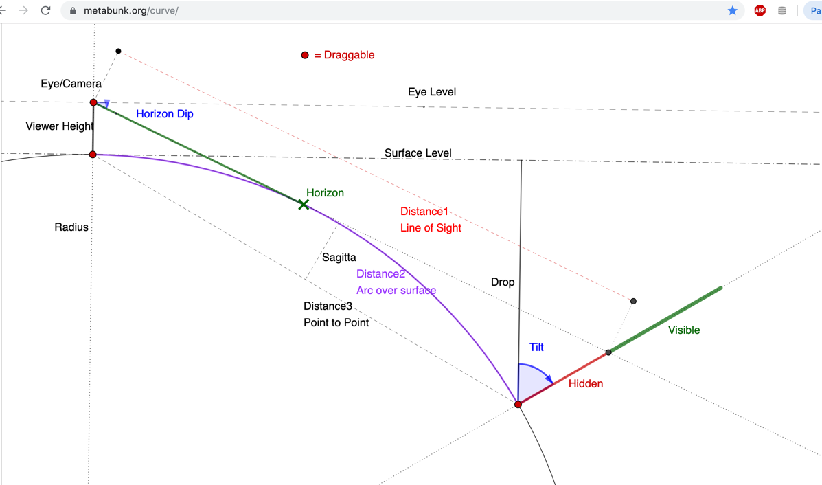
Based on our globe earth, an observation point at 626 meters above sea level has their visible horizon 96.47 km away. Not considering atmospheric influence, that is the greatest possible distance. Dubrechen is not visible by direct line-of-sight.
-
http://www.l-com.com/content/Wireless-Calculators.html
- - - - - - - - - - - - - - - - - - - - - - - - - - - - - - - - - - - - - - - - - - - - - - - - - - - - - - - - - - - - - - - - - - - - - - - - - - - - -
Basic microwave information...
Drawbacks or disadvantages of Microwave frequency
Following are the disadvantages of Microwave frequency:
As it travels in line of sight, it is affected by obstacles such as mountains, tall buildings etc. This has to be taken care in RF budget planning.
The microwave frequencies are attenuated due to various parameters such as rain, snow, fog etc.
The microwave frequencies are reflected from flat & metal surfaces.
It is diffracted from solid objects.
-
The shorter wavelength of a 5GHz signal (about half the size of a 2.4 GHz signal) causes it to collide more often with atoms in its path (scattering), leading to greater power loss (attenuation). In a vacuum, there is no loss of power / penetration.
2.5 GHz = 0.11991698 meters = 11.991698 cm
5 GHz = 0.05995849 meters = 5.995849 cm
-
How far can microwave signals travel?
A microwave link is a communications system that uses a beam of radio waves in the microwave frequency range to transmit video, audio, or data between two locations, which can be from just a few feet or meters to several miles or kilometers apart.
-
The 2.4 GHz band provides coverage at a longer range but transmits data at slower speeds. The 5 GHz band provides less coverage but transmits data at faster speeds. The range is lower in the 5 GHz band because higher frequencies cannot penetrate solid objects, such as walls and floors
-
What is the difference between 2.4 GHz and 5 GHz wireless frequencies?, by (kb.netgear.com)
https://kb.netgear.com/29396/What-is-the-difference-between-2-4-GHz-and-5-GHz-wireless-frequencies
The primary differences between the two frequencies are the range (coverage) and bandwidth (speed) that the bands provide. The 2.4 GHz band provides coverage at a longer range but transmits data at slower speeds. The 5 GHz band provides less coverage but transmits data at faster speeds.
The range is lower in the 5 GHz band because higher frequencies cannot penetrate solid objects, such as walls and floors. However, higher frequencies allow data to be transmitted faster than lower frequencies, so the 5 GHz band allows you to upload and download files faster.
Your WiFi connection on a particular frequency band can also be faster or slower because of interference from other devices. Many WiFi-enabled technologies and other household devices use the 2.4 GHz band, including microwaves and garage door openers. When multiple devices attempt to use the same radio space, overcrowding occurs. The 5 GHz band tends to have less overcrowding than the 2.4GHz band because fewer devices use it and because it has 23 channels for devices to use, while the 2.4GHz band has only 11 channels. The number of channels that are available to you depends on the regulatory domain. If you’re experiencing a lot of interference from other devices, consider using the 5 GHz band.
-
Microwaves travel solely by line-of-sight paths; unlike lower frequency radio waves, they do not travel as ground waves which follow the contour of the Earth, or reflect off the ionosphere (skywaves). Although at the low end of the band they can pass through building walls enough for useful reception, usually rights of way cleared to the first Fresnel zone are required. Therefore, on the surface of the Earth, microwave communication links are limited by the visual horizon to about 30–40 miles (48–64 km). Microwaves are absorbed by moisture in the atmosphere, and the attenuation increases with frequency, becoming a significant factor (rain fade) at the high end of the band. Beginning at about 40 GHz, atmospheric gases also begin to absorb microwaves, so above this frequency microwave transmission is limited to a few kilometers. A spectral band structure causes absorption peaks at specific frequencies (see graph at right). Above 100 GHz, the absorption of electromagnetic radiation by Earth's atmosphere is so great that it is in effect opaque, until the atmosphere becomes transparent again in the so-called infrared and optical window frequency ranges.
https://en.m.wikipedia.org/wiki/Microwave
- - -
Published on – October 2, 2019
Discussion at - https://www.youtube.com/channel/UC7ipUKERU0tzYFxALJBli4A/discussion
Our home page all articles - http://flatearthlunacy.com
kind regards, JonahTheScientist